The right structures to beat the heat
The PIP-II linear accelerator uses superconducting radio-frequency technologies to accelerate the particle beam. SRF technologies offer significant performance advantages, directly supporting the unique capabilities of PIP-II to deliver high beam intensities in continuous wave mode, with flexible beam patterns.
Particle beams are accelerated with electric fields. These electric fields oscillate, and metallic structures sustain them. In the presence of an oscillating field, electric currents flow within the metallic walls of these structures, and in most cases, these electric currents generate heat. This is the same thing that happens when an electric current flows through the coils on an electric stove. This heating negatively affects accelerator performance in two ways:
- A lot of the energy delivered to the accelerating structures is converted into heat inside the structure walls instead of being imparted to the particle beam. This may make an accelerator inefficient.
- Removing the heat from the structures is a daunting task that would generally result in the linac only being “on” about 1% of the time. This eliminates any potential for continuous wave operations, the ability to deliver the beam continuously.
But both limitations are overcome with superconducting accelerator structures. Superconducting radio-frequency cavities accelerate particle beams in a highly efficient way — making it possible to accelerate intense proton beams to higher energies in relatively short distances. In addition, superconducting radio frequency is the only technology that supports continuous wave operation.
What follows describes how PIP-II works in more detail.
How perfect niobium cavities help particles ride the waves down the linac
Because of the property of electrical resistance, electric currents flowing in metallic structures generate heat. At everyday temperatures, or room temperature, all metal conductors have resistance. However, certain metals lose all electrical resistivity when cooled to ultra-low temperatures.
One such material is the element niobium. When cooled to less than about 4 degrees above absolute zero — 4 kelvins or -452 degrees Fahrenheit, a temperature almost as cold as outer space, niobium loses electrical resistance. The PIP-II accelerating structures are made of pure niobium, which means energy isn’t lost to heat. The structures are cooled to 2 kelvins by bathing them in liquid helium.
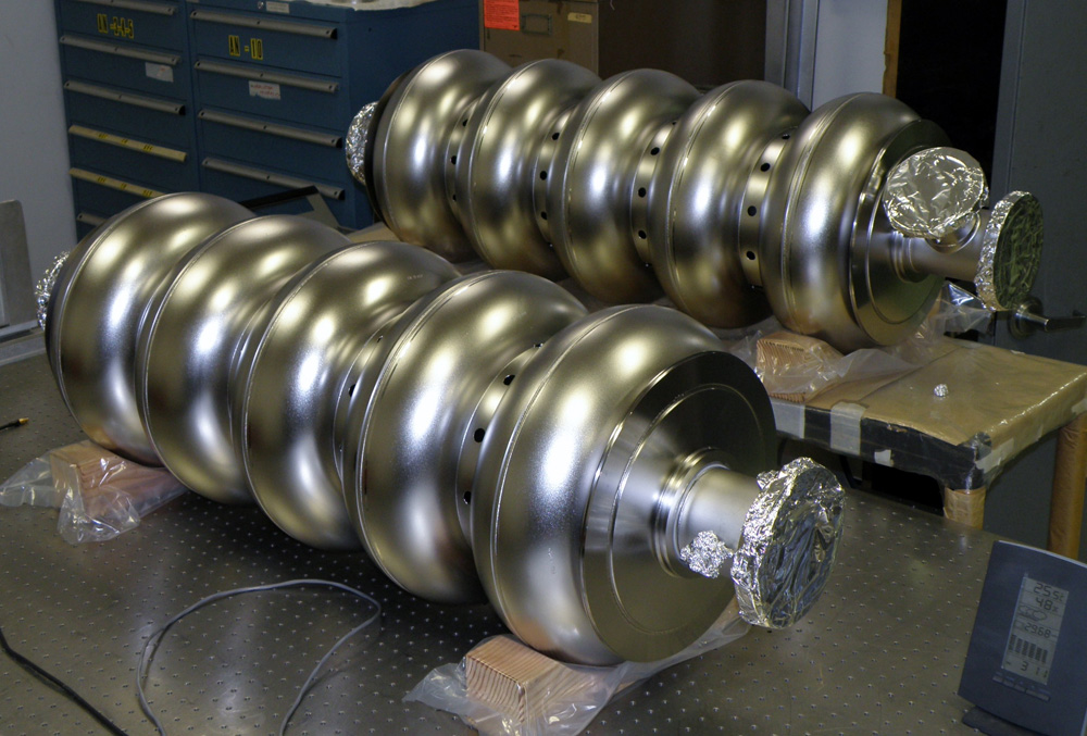
A powerful radio-frequency source generates the electric fields that accelerate the particle beam; the beams are sustained in niobium structures called cavities. To achieve the desired performance, each cavity has carefully-processed surfaces and is assembled in particulate-free clean rooms. Each cavity consists of either one or several cells that sustain the electric fields in an oscillating pattern.
These oscillations are timed so that each time an H-minus ion enters a new cell the ion lands on the wave in a way that gives the beam a positive acceleration, which pushes the proton to the next cell. This process continues until the particle has shot all the way through the accelerator.
This is how the H-minus ions can ride the waves from cell to cell down the entire length of the linac.
Thermos-like vessels serve as hospitably cold homes for strings of cavities
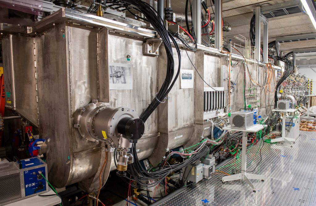
A number of cavities, ranging from three to eight, are assembled into a unit called a cryomodule. In PIP-II, 23 cryomodules house 116 cavities. The cryomodule supplies the required liquid helium bath and insulates the cavities from the too-warm outside world, a bit like a thermos bottle.
PIP-II uses five different types cavities, with each type designed to efficiently accelerate H-minus ions of a particular velocity. The cavities are grouped into three families: half-wave, single-spoke and elliptical.
Each cryomodule houses cavities that share a given family.
The first cryomodule in the linac houses the half-wave resonators, or HWR. It is located downstream from the radio-frequency quadrupole and accepts the particle beam at 2.1-million-electronvolts, or 2.1 MeV. The HWR cryomodule operates at a frequency of 162.5 Megahertz, the same as the radio-frequency quadrupole. Designed and fabricated at Argonne National Laboratory in Illinois, this cryomodule is now in operation at the PIP-II Injector Test facility, or PIP2IT, at Fermilab. The particle beam exits this cryomodule with an energy of about 10 MeV.
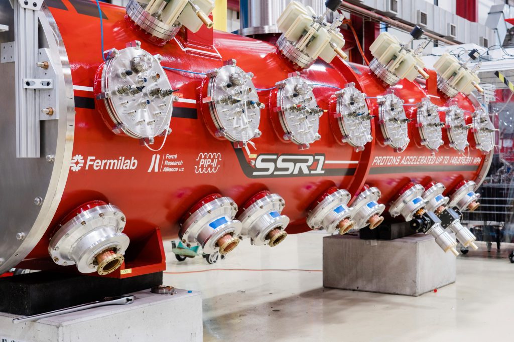
Next come nine cryomodules that house single-spoke, or SSR, resonators. Two slightly different cavity resonators, imaginatively named SSR1 and SSR2, accommodate the beam’s changing velocity as it is accelerated. These two cryomodule types accept the H-minus beam from the HWR cryomodule at 10 MeV and operate at a frequency of 325 MHz, double the frequency of that first cryomodule. Teams at Fermilab and at laboratories in France and India are designing and fabricating SSR1 and SSR2 cryomodules. (A prototype of the SSR1 cryomodule is currently under test at PIP2IT.)
The particle beam exits the final SSR2 cryomodule with an energy of 185 MeV.
Thirteen cryomodules that house elliptical cavities do the final accelerating. Again, two slightly different cavity shapes, named LB650 and HB650, accommodate the beam’s changing velocity. These cryomodules accept the H-minus beam from the SSR2 cryomodule at 185 MeV and operate at a frequency of 650 MHz, doubling the frequency once more. Teams at laboratories in France, India, Italy and the United Kingdom are designing and fabricating the LB650 and HB650 cryomodules.
At the end of the final HB650 cryomodule, the particle beam reaches its full energy of 800 MeV and has shot all the way through the accelerator.